
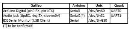
Before making the project, I assume to you know about ESP8266 Wi-Fi module(inexpensive compared to other wifi modules and it has a MCU. For these reasons, it is motivation on IoT products for me) and you have one. I am new on ESP8266 and I have a Intel Galileo Gen1 and no USB – TTL converter or an Arduino. So I need to communicate with ESP8266 via Intel Galileo but SoftwareSerial library which is used for Arduino-ESP8266 examples does not work on Galileo. Arduino can be also used to communicate with ESP8266 and most of examples SoftwareSerial library is used to create Serial port which is used to cummunicate with ESP8266, although SoftwareSerial library is available on Arduino IDE for Intel Galileo, the library does not work. Fortunately, Galileo has a Serial port on Tx/Rx pins which is numbered 1 and 0 respectively on the board. Galileo has 3 Serial channels that one channel called ‘Serial’ is IDE Serial Monitor on USB client which is used to comminicate with Galileo at Serial Port Monitor on Arduino IDE, the other port called ‘Serial1’ or UART0 which is used to communicate with a device via Tx and Rx pins on the board. Rx pin is numbered as 0, and Tx pin is numbered as 1 you know. And the other port called ‘Serial2’ or UART1 which is available on 3.5mm jack port.The Serial2 is used to access the linux terminal of the board. You can read detailed article about preparing a 3.5 mm jack cable which will be used to access linux terminal of the board via your PC. This is called serial port communication. The communication is between your PC and the board.
We will use UART0 port over pin0:Rx and pin1:Tx for communication. AT commands will be send at Serial Port Monitor on Arduino IDE via ‘Serial’ and, Galileo will send these commands to ESP8266 over ‘Serial1’ ,then returning of the commands which is responding of ESP8266 module will be send over the same way to the Serial Port Monitor on Arduino IDE. The main process like this.
ESP8266 Pın Configuration;
Tx pin of ESP8266 connected to pin0:Rx on the Galileo board,
Rx pin of ESP8266 connected to pin1:Tx on the Galileo,
Vcc pin of ESP8266 to Galileo’s 3.3V output(Attention! not to 5V),
CH_PD of ESP8266 to Galileo’s 3.3V(you can use a breadboard to short CH_PD and VCC pins of ESP8266). CH_PD pin is enable pin for the module so that you must supply high signal to this pin.
GND pin of ESP8266 to Galileo’s ground pin,

In addition, you can use a capacitor for VCC and CH_PD pins to avoid voltage changes or a 3.3V regulator may be used. If a 3.3V regulator is used, you watch out that there is a term which is called dropout voltage on regulator so you must use 5Vpin of Intel Galileo for supplying reference voltage to the regulator. Regulator has 3 pins; 5V input pin, a ground pind and a 3.3v output pin.
After making required connections, connect your Galileo to your PC and Run Arduino IDE. I have used Arduino whose version 1.5.3. The required code is here,
Required codes;
</pre>
//yildirimsemih.wordpress.com

//These commands have be coded for communinating with ESP8266 via Intel Galileo
//whole article and required pin configuration between Galileo and ESP8266
//is available on yildirimsemih.wordpress.com
//Rx of ESP8266 to Galileo's pin1:Tx
//Tx of ESP8266 to Galileo's pin0:Rx
//VCC and CH_PD of ESP8266 to Galileo's 3.3V voltage output
//GND to GND

String a = "";
char c;
char k;
void setup() {
Serial1.begin(115200);
Serial.begin(115200);
}

void loop() {

if(Serial1.available()){ // if ESP8266 is available on Serial1

while(Serial1.available()){// while it is available
c = Serial1.read();  //listen to Serial1(ESP8266) character by character and assign to c
a += c;              // assign c to string a
}
Serial.print(a);      //print the responding of ESP8266
a = "";               // empty the string a
}

if(Serial.available()){     //if USB client is available on Serial Port Monitor(Serial)
delay(2000);          // delay is required to whole reading of your command
// which will be send to ESP8266
String yourcommand=""; //create empty string for storing your command
while(Serial.available()){ // while Serial is available
k = Serial.read();     //listen to Serial Port Monitor on IDE(Serial)
// character by character and assign to k
yourcommand += k;       // assign each char k to yourcommand
}
Serial1.println(yourcommand); // send the read character to ESP8266
}
}
<pre>
You need to fix the code after pasting on Arduino sketch for quates. Check the whole code after pasting.
According to firmware version your ESP8266 module, you should need to change baudrate.
Open Serial Port Monitor on IDE Baudrate of Serial Port Monitor on Arduino IDE is the same with Serial1 baud rate and additionaly CR (Carriage Return) should be selected.Type test command “AT”. Respond should be “OK”, if you have done correctly.
“AT+GMR” can be used for determining the firmware version of your module,
“AT+RST” is used to reset the module,
“AT+CWLAP” for listing the access points which the module can receive,(if you burn a firmware your ESP8266, you need to use mode of the module by typing “AT+CWMODE=1”. Mode1 set up ESP8266 for joining a router)
“AT+ CWJAP =<ssid>,< pwd >” for join an access point, ssid is access point’s ssid and password is password of it,
“AT+CWJAP?” is used to see joined access point ssid or you can check whatever ESP8266 is connected to the your wi-fi network by opening your router web interface on browser.
“AT+CIFSR” ic used to check the assigned IP adress to ESP8266 by router.


Please report bugs on applying the above steps!


Sketch uses 262656 bytes (52%) of program storage space. Maximum is 499696 bytes.
Global variables use 26672 bytes (32%) of dynamic memory, leaving I cannot connect to wifi, and I get this error message:
55248 bytes for local variables. Maximum is 81920 bytes.
esptool.py v2.6
2.6
esptool.py v2.6
Serial port COM3
Connecting…….._____….._____….._____….._____….._____….._____….._____
Traceback (most recent call last):
File “C:\Users\anneb\Documents\ArduinoData\packages\esp8266\hardware\esp8266\2.5.1/tools/upload.py”, line 25, in
esptool.main(fakeargs)
File “C:/Users/anneb/Documents/ArduinoData/packages/esp8266/hardware/esp8266/2.5.1/tools/esptool\esptool.py”, line 2653, in main
esp.connect(args.before)
File “C:/Users/anneb/Documents/ArduinoData/packages/esp8266/hardware/esp8266/2.5.1/tools/esptool\esptool.py”, line 468, in connect
raise FatalError(‘Failed to connect to %s: %s’ % (self.CHIP_NAME, last_error))
esptool.FatalError: Failed to connect to ESP8266: Invalid head of packet (0x07)
esptool.FatalError: Failed to connect to ESP8266: Invalid head of packet (0x07)
BeğenBeğen
Please check your COM port number on Device Manager. May be your device is not connected to COM3
BeğenBeğen